

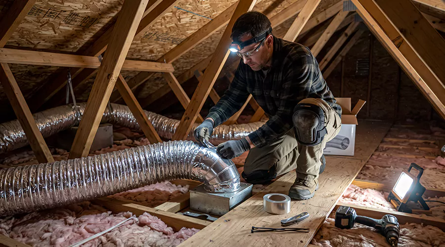
Installing flexible ductwork involves designing a suitable duct route, selecting the correct diameter, attaching the inner liner securely to connection collars, sealing the joints, and supporting the duct without excessive sagging or compression. The insulation and exterior vapor barrier must also be restored at each connection. After installation, the HVAC system should be checked for air leakage and appropriate airflow.
Flexible ductwork, commonly called flex duct, is widely used in residential heating and cooling systems. It often connects a rigid main supply trunk to ceiling or floor registers, although suitable flexible products may also be used in other approved duct configurations. The material can follow gentle curves around building framing without requiring a separate metal elbow at every change of direction.
A typical insulated flexible duct contains an inner liner supported by a spiral wire, a surrounding insulation blanket, and an exterior protective jacket. The inner liner carries air, while the insulation limits heat transfer and the jacket protects the insulation. Proper HVAC ductwork installation must account for all these layers because each performs a different function.
Although flexible ducts are easier to route than rigid metal in certain situations, they are sensitive to installation errors. Excessive length, sharp bends, and inadequate supports increase resistance to airflow. Correct sizing and careful installation are therefore necessary for a new flexible duct system to deliver the intended amount of conditioned air.
What Is Flexible Ductwork?
Flexible ductwork is a bendable air passage used in heating, ventilation, and air conditioning systems. Most residential products use a plastic or foil-based inner liner supported by a wire helix. Insulated versions include fiberglass blanket insulation and an outer jacket that may also serve as a vapor barrier.
Flexible ducts are available in several diameters and insulation ratings. Common insulated products are available in R-4, R-6, and R-8 configurations, although local codes may require specific ratings for particular locations. The correct product depends on the air distribution design and the conditions surrounding the installation.
Flex duct is especially useful for connecting a main trunk to a room outlet through an accessible attic. However, the material should not be used where it will be crushed or exposed to conditions outside its listing. Large trunks and high-temperature equipment connections may require other materials.
Where Can You Install Flexible Ductwork?
Flexible ductwork is used in residential attics, crawlspaces, and certain approved ceiling or floor spaces. The material is convenient where a short branch must pass around framing or connect to a register at a different angle. Its suitability depends on providing enough clearance for the full insulated diameter.
| Installation Location | Main Consideration |
|---|---|
| Vented attic | Insulation, support, and heat exposure |
| Crawlspace | Moisture protection and clearance above ground |
| Unfinished basement | Suitable supports and protection from damage |
| Ceiling cavity | Available clearance and building requirements |
| Return air branch | Correct sizing and airtight connections |
| Main distribution trunk | Requires design and product suitability review |
Flexible ductwork should not automatically replace rigid metal near heating equipment. Products have temperature limits and installation restrictions that must be followed. The contractor should identify the appropriate duct material for each part of the system.
Whenever practical, placing the ductwork inside the home's conditioned space can reduce unwanted heat transfer. When installation in an unconditioned attic or crawlspace is unavoidable, suitable insulation and vapor protection become particularly important.
What Tools and Materials Are Needed to Install Flexible Ductwork?
The installation requires more than the flexible duct itself. Connection collars, sealing materials, and supports are necessary to create an airtight and stable air passage. All products should be appropriate for the duct manufacturer and applicable HVAC standards.
| Material or Tool | Purpose |
|---|---|
| Correctly sized insulated flexible duct | Carries conditioned air |
| Approved metal takeoff collars | Connects flexible duct to rigid equipment |
| Register boots or diffuser boxes | Connects branches to room openings |
| Mechanical drawbands | Secures the inner duct liner |
| Compatible drawband tensioning tool | Tightens the connection fasteners |
| HVAC mastic | Seals suitable duct-collar joints |
| Listed UL 181 closure products | Seals approved duct connections |
| Wide support straps or saddles | Prevents sagging and compression |
| Tape measure | Measures duct routes and lengths |
| Suitable utility knife and wire cutter | Prepares duct material |
| Protective gloves and eye protection | Reduces handling injuries |
| Flashlight and inspection equipment | Checks routing and connections |
The correct sealing method depends on the product. Ordinary cloth-backed duct tape should not be used as the permanent connection seal. The Department of Energy recommends mechanical attachment of the inner liner and suitable sealing before the insulation and exterior jacket are restored.
How Do You Choose the Correct Flexible Duct Size?
Flexible duct diameter should be based on the airflow required at the connected room outlet. A duct that is too small can create resistance and reduce delivered air. An excessively long route with multiple bends may also need a different design from a short direct branch.
ACCA Manual D provides recognized residential duct-sizing principles. The design considers the required airflow, available static pressure, duct material, fittings, and effective duct length. Flexible duct compression and sagging are important because they can increase resistance substantially.
A contractor should determine the required diameter before purchasing material or cutting openings. Typical residential branches may use several different diameters within the same house. Room size alone does not establish the correct duct size because heating and cooling loads vary with insulation, windows, and other building conditions.
The chosen duct must also match the connection fittings. A correctly designed diameter should not be reduced abruptly simply to attach to an existing smaller collar.
How to Plan a Flexible Duct Layout
A good flexible duct layout uses relatively short, direct runs with gentle changes in direction. The installer should identify the main trunk, intended takeoff location, and register boot before measuring the required length. The route must provide adequate clearance for the fully insulated duct.
Avoid planning a path that requires the material to be squeezed beneath framing. A tight bend can compress the inner liner and reduce airflow. Where a suitable flexible curve is not possible, a rigid elbow or redesigned route may provide better performance.
The layout should also include support locations. A flexible duct cannot simply be laid across obstructions or suspended by its connections. Proper support is part of the design rather than a correction made after the duct begins sagging.
How to Install Flexible Ductwork Step by Step?
The following procedure explains the typical installation of an insulated residential flexible duct branch. The process should follow the specific product manufacturer's instructions and applicable mechanical and energy codes. New branches, main duct changes, or complex installations should be designed and completed by qualified HVAC personnel.
Step 1. Calculate the Airflow Requirement
Determine the amount of air the connected room needs before selecting a duct. The calculation should consider the room's heating and cooling loads and the available airflow from the HVAC equipment. It should also account for resistance in the existing trunk and other branches.
ACCA Manual D is commonly used to select residential duct dimensions. A branch should not be sized solely by copying a nearby duct because rooms can have different airflow requirements. A proper design helps prevent excessive noise and weak room airflow.
Step 2. Identify the Supply or Return Connection
Locate the intended connection point at the main trunk, junction box, or return system. The fitting must be suitable for the designed duct diameter and the airflow being carried. Inspect the surrounding duct for structural damage and determine whether it can accept another connection.
Adding a branch to an existing system can change the airflow available elsewhere. The contractor should confirm that the equipment and main duct can support the proposed arrangement. Installing a new takeoff without checking system capacity may reduce airflow to other rooms.
Step 3. Plan the Installation Route
Mark the intended duct path from the connection collar to the room register. The route should be as direct as practical without forcing the duct through restricted spaces. Allow enough room for the insulation and exterior jacket around the inner passage.
Sharp turns immediately after fittings should be avoided. The Department of Energy recommends supporting the duct between a rigid connection and a bend so the liner can leave the collar without becoming pinched. Planning this transition before installation reduces later adjustments.
Step 4. Prepare the Work Area
Inspect the attic, basement, or crawlspace for access hazards. Attic ceiling drywall cannot support workers, and crawlspaces may contain water or electrical hazards. Safe access and suitable lighting are necessary before materials are moved into position.
Check the surrounding insulation and building materials. Older duct wrapping or attic insulation may require specialized assessment when asbestos-containing material is suspected. Do not disturb unfamiliar potentially hazardous materials during ordinary installation.
Step 5. Shut Down the HVAC System
Turn off the equipment before making connections to the duct network. The blower should remain off while openings are exposed to the work area. This helps prevent loose construction debris from being drawn into or distributed through the system.
Qualified personnel should follow appropriate electrical isolation procedures when the installation requires access to equipment cabinets. Fuel-burning furnace exhaust components must also remain separate from ordinary air distribution work. A flexible room-air duct should never be connected to a combustion flue.
Step 6. Install the Takeoff Collar
Attach an approved takeoff collar to the rigid supply trunk or other suitable fitting. The collar should match the duct design and provide a stable connection for the flexible inner liner. It must be mechanically secured according to the fitting and duct manufacturers' requirements.
Where a new opening is required in existing metal ductwork, the work should be performed without leaving sharp edges that can damage the liner. The connection around the fitting should also be sealed appropriately. A loose takeoff collar can leak or pull away under the weight of the branch.
Step 7. Install the Register Boot or Diffuser Box
Position the register boot at the intended floor, wall, or ceiling opening. The boot should be securely supported and correctly aligned with the room register. Its connection collar must match the designed duct size.
The boot-to-building connection should also be considered. Gaps where the boot meets a ceiling or floor can allow unwanted air movement between building spaces. Suitable sealing helps limit those losses.
A properly supported register boot should not rely on the flexible duct to hold it in position. The duct and outlet fitting need independent support where required.
Step 8. Measure the Flexible Duct Length
Measure the route between the connection points while accounting for gentle bends. Do not add unnecessary extra length as a precaution. Excess flexible duct can form loops or sagging sections that increase airflow resistance.
The Department of Energy recommends stretching flexible duct appropriately so the inner liner does not remain compressed. The required length should match the planned route rather than a rough straight-line estimate. A properly sized branch has enough material for suitable connections without excessive slack.
Step 9. Cut and Prepare the Duct
Prepare the flexible duct to the measured length using suitable cutting tools. The outer jacket and insulation must be handled separately from the inner liner and reinforcing wire. Cut the liner without tearing the surrounding material.
The duct manufacturer's instructions should determine how much liner is exposed for the connection. A clean and undamaged end makes it easier to install the drawband and seal the joint. If the liner becomes torn during cutting, correct the damage before continuing.
Step 10. Attach the Inner Liner to the First Collar
Move the exterior jacket and insulation back far enough to expose the inner liner. Position the liner over the metal collar according to the product instructions, typically beyond the collar's retaining bead. The inner passage should remain circular and properly aligned.
Secure the liner with an approved drawband or mechanical fastener. Tighten it using the appropriate tool so the liner stays attached without being cut or damaged. The exterior jacket should not be used as a substitute for fastening the inner air-carrying layer.
Step 11. Seal the Inner Duct Connection
Apply suitable HVAC mastic or another approved closure product at the liner-to-collar connection. The objective is to prevent conditioned air from escaping through the joint. Mechanical attachment and air sealing are separate requirements, so both should be completed.
The Department of Energy's Building America guidance describes sealing the flexible liner connection with mastic after fastening it to the collar. Product-specific instructions may identify an approved alternative. The joint should be inspected before the insulation is pulled back over it.
Step 12. Restore the Insulation and Vapor Barrier
Pull the insulation over the collar and connection so the joint remains thermally protected. Avoid leaving gaps that expose the duct or compressing the insulation excessively. Insulation thickness affects thermal performance, particularly in unconditioned spaces.
Bring the exterior jacket over the insulated connection and seal it as directed by the product manufacturer. Listed closure tape or mastic may be appropriate for the jacket. The finished connection should maintain the intended protective and vapor-barrier continuity.
Step 13. Extend the Duct Along the Planned Route
Carefully position the duct along the planned path. Keep the inner liner extended without twisting it or forcing it into sharp bends. A flexible duct should not be compressed against framing or other building equipment.
Where the route changes direction, use a gentle curve with suitable support. Long sagging sections create additional resistance. If the duct cannot maintain its shape, modify the route or use a suitable rigid fitting.
Step 14. Attach the Other End
Connect the remaining end to the register boot, return box, or other approved fitting. Repeat the mechanical inner-liner fastening and sealing procedure. Restore the insulation and exterior jacket around the second connection.
The duct should not be stretched so tightly that it pulls on the collars. It should also not have excess slack forming an unnecessary loop. Inspect both connection points after the duct is positioned.
Step 15. Install Horizontal Supports
Install approved support straps or saddles along the duct route. Department of Energy guidance recommends support spacing no greater than four feet for typical horizontal flexible ducts, with supports at least 1.5 inches wide. Sag should be limited to approximately half an inch per foot between supports.
The supports must not compress the duct's insulation or inner liner. Tight narrow straps can distort the passage and increase resistance. Additional support may be necessary immediately before and after bends.
Connection collars should not be expected to support the entire duct's weight. Suitable framing or other approved structural support points should carry the load.
Step 16. Support Vertical Sections Correctly
Vertical flexible duct sections require a support arrangement appropriate for their length and construction. Department of Energy guidance calls for vertical support intervals no greater than six feet under typical conditions. The manufacturer's instructions may impose more specific requirements.
The weight of a long vertical section should not pull directly against a single fitting. Proper support helps prevent the liner and jacket from separating or becoming damaged. The route must also comply with applicable building penetration and fire-safety requirements.
Step 17. Inspect Bends and Connections
Examine the entire run after supports are installed. Check for tight bends and pinched areas near joists or fittings. Verify that the duct remains extended and that no support strap has compressed the air passage.
Inspect both end connections to confirm that the inner liner remains attached and the exterior jacket is sealed. Nearby construction work may shift the duct after its initial placement. Correcting these problems before equipment startup is easier than after access becomes limited.
Step 18. Check Air Leakage
A qualified contractor should evaluate the duct connection for leakage. A duct pressurization test may be required or appropriate, particularly when multiple branches have been installed. Visual inspection alone may not reveal every small opening.
If leakage is detected, inspect the collars and seams before adding sealant indiscriminately. Mechanical connections should remain secure. Any corrections should use materials approved for the duct system.
Step 19. Verify Room Airflow
Restore HVAC operation only after all ducts and equipment panels are properly connected. The installer should verify airflow at the room register and check whether the system operates within appropriate pressure conditions. This helps identify a restrictive duct route or inadequate branch sizing.
A new duct does not automatically deliver the intended airflow merely because air can be felt at its outlet. Measuring airflow provides stronger evidence. Any balancing adjustments should follow the system design.
How Far Apart Should Flexible Duct Supports Be?
The Department of Energy recommends that typical horizontal flexible duct supports be installed no more than four feet apart. Support straps should be at least 1.5 inches wide, and sag should not exceed approximately half an inch per foot. Vertical ducts generally require supports at intervals no greater than six feet.
These are common guidance values, not permission to ignore product-specific requirements. Some installations may need closer supports because of bend geometry or other conditions. Supporting the duct near its connection points helps prevent the liner from being pulled sharply against a metal collar.
Support straps should distribute the duct's weight rather than squeeze its insulation. When the duct is crushed at a support point, the effective airflow passage becomes smaller. The correct installation preserves the duct's shape along its entire length.
Can Flexible Ductwork Rest on the Attic Floor?
Flexible ducts can rest on approved supporting surfaces in certain attic installations, but the arrangement must account for climate, insulation, and moisture conditions. The Department of Energy describes different strategies for dry and humid climates. A method that works in one type of attic may create condensation risks in another.
The duct should remain protected from crushing and maintain the manufacturer's support requirements. Contact with surrounding materials should not deform the inner passage. The exterior jacket and insulation must remain intact.
The contractor should evaluate whether suspending the ducts or using a carefully designed attic-floor installation is more appropriate. Duct placement should be considered with the attic's thermal boundary and insulation strategy.
How Do You Connect Flexible Ductwork to Metal Ducts?
Flexible ducts are commonly attached to metal takeoff collars or rigid transitions. The inner liner should fit over the collar and be held using approved mechanical fastening. The connection is then sealed with a compatible duct-sealing product.
After the inner air passage is secured, the insulation and outer jacket are restored over the joint. These exterior layers protect the connection but should not be mistaken for the air-carrying liner. A connection made only to the outside jacket can leak substantially.
A suitable rigid connector is also needed when joining two flexible duct sections. Overlapping the liners and wrapping them with ordinary tape is not an appropriate replacement for a proper fitting.
How Much Does Flexible Ductwork Installation Cost?
Angi's 2026 pricing estimates place flexible ductwork at approximately $10 to $18 per linear foot for certain residential installation or replacement projects. The actual cost depends on the duct size, insulation rating, labor, and access conditions. Larger projects may involve additional design and equipment connections.
A short branch in an accessible attic may cost less than a similar duct installed through restricted framing. Material prices alone do not include the full work required to fasten, seal, and support the duct. Professional quotes should identify those components.
If a new branch is being added to an existing HVAC system, the contractor should also evaluate whether the equipment and duct network can support the added airflow. This is different from replacing an existing branch with an equivalent correctly sized section.
What Are the Most Common Flexible Duct Installation Mistakes?
Many flexible duct performance problems result from installation rather than the material itself. Excessive compression and poorly positioned supports can restrict airflow soon after the system is installed. Loose connections can also release conditioned air into unfinished spaces.
Avoid these errors:
- Selecting duct diameter without airflow calculations.
- Leaving the inner liner compressed.
- Installing unnecessary long loops.
- Creating sharp bends immediately after metal collars.
- Forcing the duct through restricted framing.
- Using narrow supports that compress the insulation.
- Allowing long unsupported sections to sag.
- Securing only the exterior jacket.
- Failing to seal the inner duct connection.
- Using ordinary cloth-backed tape for permanent duct sealing.
- Leaving gaps in the vapor barrier.
- Supporting the duct from unsuitable utilities.
- Installing products outside their temperature or application ratings.
- Ignoring return-air requirements.
- Skipping leakage and airflow testing.
These errors can reduce performance even when all the materials are new. An appropriately designed and installed branch should maintain its shape and provide a secure, airtight route from the main duct to the room.
Can You Install Flexible Ductwork Yourself?
A limited installation may be possible for an experienced homeowner when the duct route is safely accessible and the sizing has already been established. However, new branches affect the complete HVAC air distribution system. Incorrect sizing or connection methods can cause airflow restrictions and energy losses.
Attics and crawlspaces also present safety concerns, including electrical hazards and unstable access areas. Substantial installations may require permits and inspections. For new systems or changes to main trunks and returns, a qualified HVAC contractor is recommended.
A professional can also test leakage and register airflow. These measurements help determine whether the completed installation performs as intended.
How Can You Keep Flexible Ductwork in Good Condition?
Protect installed ducts from physical contact and excessive movement. Avoid placing storage items on attic branches or allowing other trades to step on flexible material. The wire-supported inner liner can become damaged even when its outer jacket looks reasonably intact.
During routine HVAC maintenance, inspect accessible supports and connections for displacement. A loose hanger should be corrected before the duct develops a deep sag or sharp bend. Moisture problems near duct insulation should also be investigated promptly.
Proper filtration and sound return connections can help control unwanted dust entering the system. Duct maintenance should focus on keeping the material dry, supported, and airtight.
Conclusion
Flexible ductwork should be installed using a properly designed route, correctly sized material, secure inner-liner connections, and suitable sealing and insulation. Wide support straps and limited sag help prevent the restrictions commonly associated with poorly installed flex ducts. The material should remain extended without excessive loops or sharp bends. The completed system should be checked for leakage and airflow. For new branches or major installations, qualified design and professional testing help prevent problems that may remain hidden after construction.